WELDED BLOCK PLATE HEAT EXCHANGERSProcess heating · Cooling · Condensation · Heat recovery
REPLACEMENT ENGINEERING

HEXCBLOC Replacement Solutions
for Compabloc® and K°Bloc® Installations

HEXCBLOC provides engineered replacement solutions for existing Compabloc® and K°Bloc® installations. Depending on the existing equipment, we can evaluate complete-unit replacement and, where technically compatible, welded-core replacement.

Each replacement is reviewed against the existing duty, dimensions, connections, materials and mechanical design requirements.

CHOOSE EXISTING EQUIPMENT

Start with the installed unit.

The model family identifies the assessment route; drawings and operating data determine the final proposal.

EXISTING EQUIPMENT

Alfa Laval Compabloc®

Series for assessmentHEXCBLOC
Complete unit + welded-core assessment

Core replacement is evaluated only where the existing geometry and interfaces are technically compatible.

For assessment: model / serial number, nameplate, GA drawing, thermal datasheet and photos.

Explore HEXCBLOC ↗
EXISTING EQUIPMENT

GEA K.BLOC / Kelvion K°Bloc®

Series for assessmentHEXCBLOC
Complete-unit assessment

Welded-core interchange is not offered for this equipment family.

For assessment: model / serial number, nameplate, GA drawing, thermal datasheet and photos.

Explore HEXCBLOC ↗
REPLACEMENT SCOPE

Confirm the duty.
Check the installation.

Complete-unit and core assessments combine process data with mechanical details.

Thermal duty

Flow rates, inlet and outlet temperatures, heat load and allowable pressure drop.

Design conditions & materials

Fluid composition, operating and design pressure and temperature, and wetted materials.

Mechanical compatibility

Overall dimensions, nozzle positions, flange standards, supports, piping interfaces and service clearances.

MODEL FAMILY REFERENCE · PRELIMINARY COMPARISON

Start with the family.
Confirm the engineering.

Model families provide a starting point. The existing duty, design conditions, drawing and installation define the replacement.

Existing equipmentHEXCBLOC familyTypical replacement routeCore replacement
Compabloc CP15 ↗HEXCBLOC 15 ↗Complete unit / core assessmentSubject to drawing and configuration review
Compabloc CP20 ↗HEXCBLOC 20 ↗Complete unit / core assessmentSubject to drawing and configuration review
K°Bloc BT20HEXCBLOC 20 ↗Complete-unit assessmentNot offered
Compabloc CP30 ↗HEXCBLOC 30 ↗Complete unit / core assessmentSubject to drawing and configuration review
K°Bloc BT30HEXCBLOC 30 ↗Complete-unit assessmentNot offered
Compabloc CP40 ↗HEXCBLOC 40 ↗Complete unit / core assessmentSubject to drawing and configuration review
K°Bloc BT40HEXCBLOC 40 ↗Complete-unit assessmentNot offered
Compabloc CP50 ↗HEXCBLOC 50 ↗Complete unit / core assessmentSubject to drawing and configuration review
K°Bloc BT50HEXCBLOC 50 ↗Complete-unit assessmentNot offered
Compabloc CP75 ↗HEXCBLOC 75 ↗Complete unit / core assessmentSubject to drawing and configuration review
K°Bloc BT75HEXCBLOC 75 ↗Complete-unit assessmentNot offered
Compabloc CP120 ↗HEXCBLOC 120 ↗Complete unit / core assessmentSubject to drawing and configuration review
K°Bloc BT120HEXCBLOC 120 ↗Complete-unit assessmentNot offered

Model size alone does not confirm interchangeability. Final selection is based on thermal duty, design pressure and temperature, materials, nozzle arrangement, dimensions and installation constraints.

Kelvion · Welded Plate Heat Exchangers · 05/25

Vertical configuration reference. CP75 is listed at 3,300 mm maximum height in the cited Alfa Laval leaflet; HEXCBLOC 75 is listed at 3,600 mm in our range. Matching family numbers or dimensions do not establish identical plate geometry, nozzle positions or thermal performance.

The cited Alfa Laval leaflet gives ASME design maxima of 30 bar for CP15–40, 38 bar for CP50–75 and 42 bar for CP120, with −46 to 343 °C. Our published HEXCBLOC range lists FV–32 bar and −40 to 300 °C. Confirm the required design conditions for each proposal.

Alfa Laval Compabloc · 200000002-1-EN-GB

PLATE PACK & CORE REFERENCE

Identify the plate configuration.

Alfa Laval spare-block references below help identify the existing core. Send its pattern, plate count, material and drawing for a HEXCBLOC core assessment.

Original modelAlfa Laval plate patternPublished plate counts
Compabloc CP15 ↗CP30 / 50 / 70 / 90
Compabloc CP20 ↗CP40 / 60 / 80 / 100
Compabloc CP30 ↗CPL60 / 80 / 100 / 130 / 160
Compabloc CP40 ↗CPK120 / 160 / 200
Compabloc CP50 ↗CPX150 / 200 / 250 / 300
Compabloc CP75 ↗CPX150–500
Compabloc CP120 ↗CPX200–500

CP75: 150 to 500 plates in increments of 50. CP120: 200 to 500 in increments of 50. These are Alfa Laval reference configurations, not a confirmed HEXCBLOC supply list.

Plate geometry

Check plate width and length, corrugation, channel gap and welded edge profile against the existing core.

Frame and panel interfaces

Confirm core envelope, panel seal faces, bolt locations and baffle arrangement. A complete spare block may include the frame as well as the welded plates.

Supply scope

Alfa Laval reference: complete unit or welded-core replacement. GEA / Kelvion reference: complete unit only; no core interchange. Confirm the selected configuration before manufacture.

Alfa Laval Compabloc Spare Block · 200011684-1-EN-GB

PLATE-EDGE WELDING GEOMETRIES

Compare edge-joint
construction.

The exact joint geometry should be confirmed from the approved manufacturer drawing for the equipment being assessed.

FORMED EDGE · BUTT WELD

Butt-welded formed edge

Butt-welded formed edgeButt weldProcess channel

The formed lips meet at a butt weld. Joint accessibility, surface continuity and cleanability depend on the approved plate profile, weld execution and service conditions.

ILLUSTRATIVE EDGE-JOINT GEOMETRY

Alternative end-welded edge geometry

Alternative end-welded edge geometryEnd weldResidual edge recessProcess channel

Depending on geometry, fluid properties and operating conditions, a residual recess may influence cleanability and deposit behaviour. The actual section must be verified from the relevant production drawing.

Assess the actual joint

Cleanability and deposit behaviour depend on the actual recess dimensions, fluid composition, temperature, alloy, weld quality, velocity and cleaning method. The schematics support an engineering discussion; they do not establish the construction or performance of a specific third-party unit.

The alternative end-welded schematic is illustrative. It is not a verified production section for a specific third-party product. Schematics are not to scale and do not show calculated flow fields.

Technical references: Alfa Laval · C-Weld · Alleima · Crevice corrosion

REPLACEMENT WORKFLOW

How we evaluate a replacement.

A defined engineering process turns the existing unit data into a project-specific replacement proposal.

01

Existing Unit

Model, nameplate, drawings and operating data.

02

Engineering Review

Thermal duty, pressure drop, materials and mechanical design.

03

Fit & Connection Check

Overall dimensions, nozzle positions, supports and piping interface.

04

Replacement Proposal

Selection sheet, GA drawing, scope, price and lead time.

REPLACEMENT REFERENCES

Project evidence from the workshop and site.

Customer names and operating details are withheld.

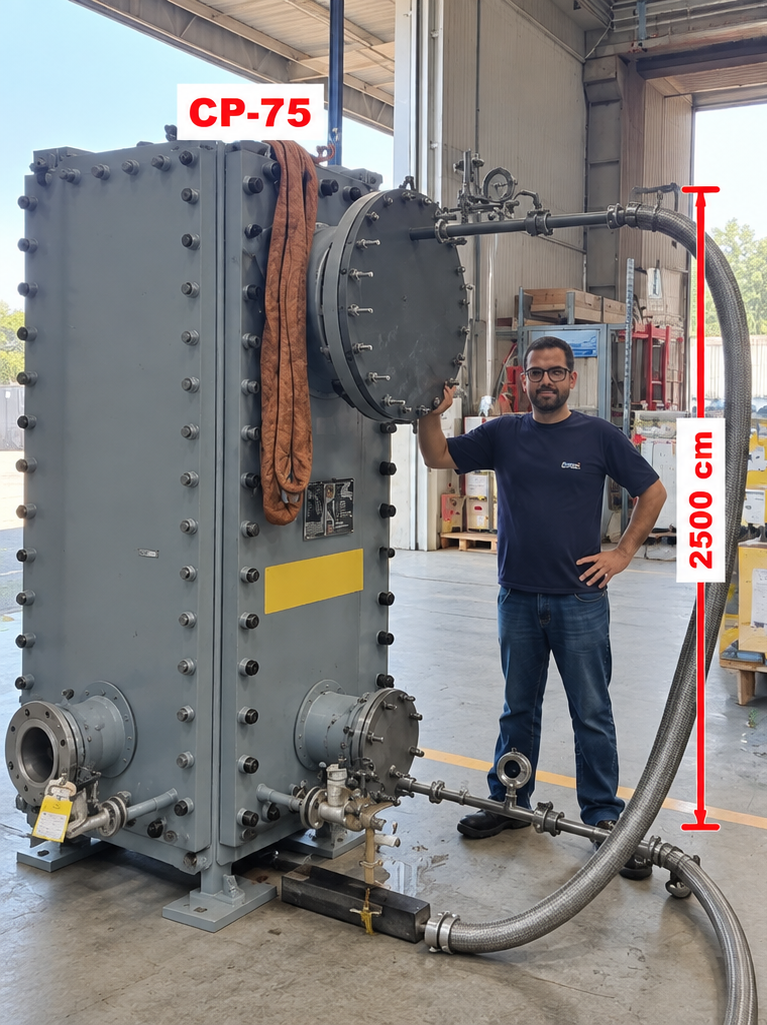
CP75 welded-core replacement assessment

Existing CP75 welded-core replacement

Existing welded block heat exchanger assessment and core replacement review.

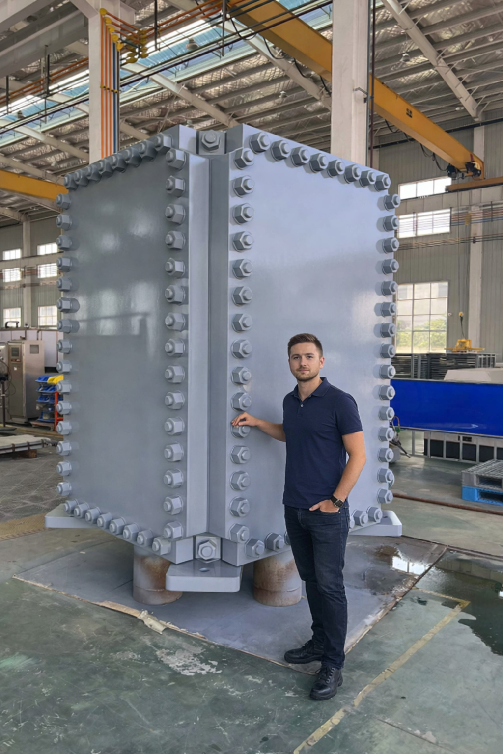
Complete-unit replacement project

Complete-unit replacement evaluation

Mechanical fit, connections and operating requirements reviewed for a complete replacement unit.

START THE ASSESSMENT

Have an existing Compabloc® or K°Bloc®?

Send us the model, nameplate, GA drawing and operating conditions. We will review the thermal duty, dimensions, connections and replacement options.