
Block plate heat exchanger
HEXCBLOC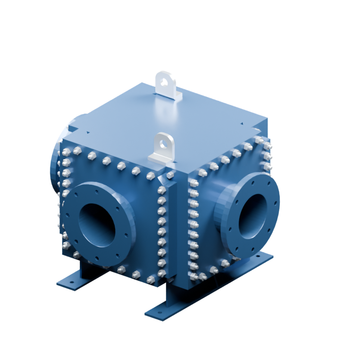
Welded metal joint
CLEANING ACCESSRemove side panels
Access to channels; the core stays welded.
Cleaning in place is also possible.Bring heating, cooling and energy recovery into your process design. Start with the duty: the plate pack, materials and flow arrangement are selected around your operating conditions.
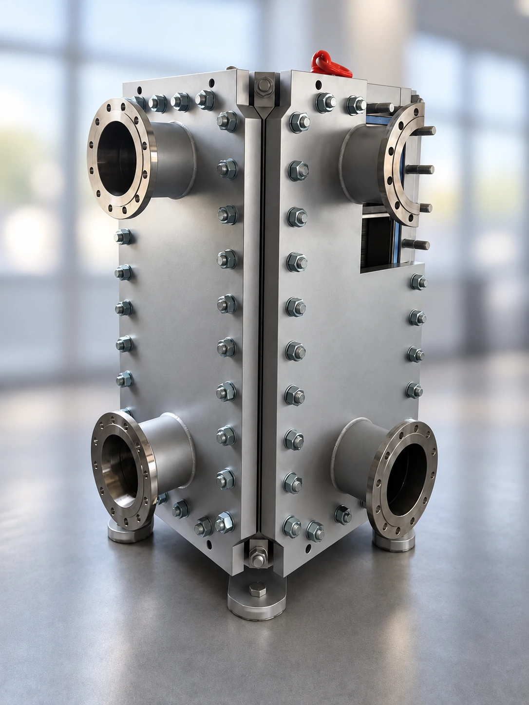 Product configuration follows project selection
See how welded construction changes temperature capability, design pressure and cleaning access compared with a gasketed plate heat exchanger.
Access to channels; the core stays welded.
Cleaning in place is also possible.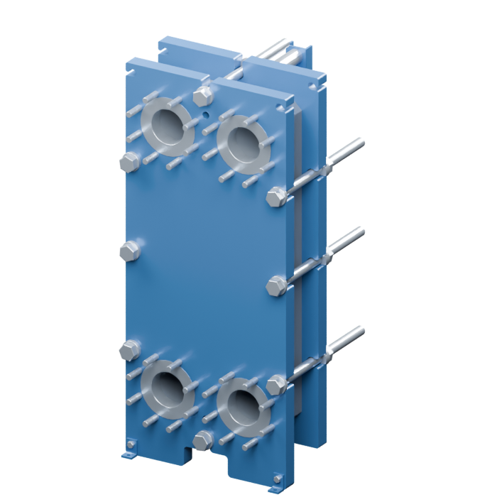
Access to individual plate surfaces.
Cleaning in place is also possible.HEXCBLOC: published standard range; final ratings depend on the approved design. Gasketed values illustrate one standard configuration; other configurations can have higher ratings.
Temperature capability depends on materials and seals. Pressure capability also depends on plate geometry, thickness, frame and design code. Maximum values do not imply simultaneous operation at both limits.
| What changes | HEXCBLOC | Gasketed plate-and-frame |
|---|---|---|
| Channel sealing | Welded plate edges; seals at the removable panels. | Elastomer gaskets around each plate and its ports. |
| Operating conditions | For demanding duties, subject to alloy, panel seals and project ratings. Published standard range: FV–32 bar, −40 to 300 °C; confirm the selected design. | Limits depend on the frame, plate design and gasket material. Check the selected model and fluid compatibility. |
| Cleaning access | Cleaning in place or access through removable panels. Individual plates remain welded into the core. | Open the frame to separate plates for individual inspection and cleaning; cleaning in place is also possible. |
| Maintenance items | Inspect panel seals, weld integrity and plate condition. No individual plate gaskets to replace. | Inspect and replace plate gaskets as needed. Individual plates can be removed and replaced. |
| Changing capacity | The welded core is sized for the duty. A capacity change requires an engineering review and may require a different core or unit. | Plates may be added or removed within frame limits, with the thermal and hydraulic design checked again. |
| Typical selection priority | Reduce reliance on inter-plate elastomer seals while keeping access through removable panels. | Convenient plate-by-plate service and flexible sizing for duties compatible with the selected gaskets. |
Rotate the equipment, separate the components and look through the plate pack. Switch to Flow principle to follow the two circuits through alternating channels.
The orange paths follow one group of channels across the plate width.
The blue paths run through the adjacent channels in the perpendicular direction. The plate walls keep the streams separate.
Heat passes through the corrugated metal plates. The flow animation illustrates direction, not calculated velocity or temperature.
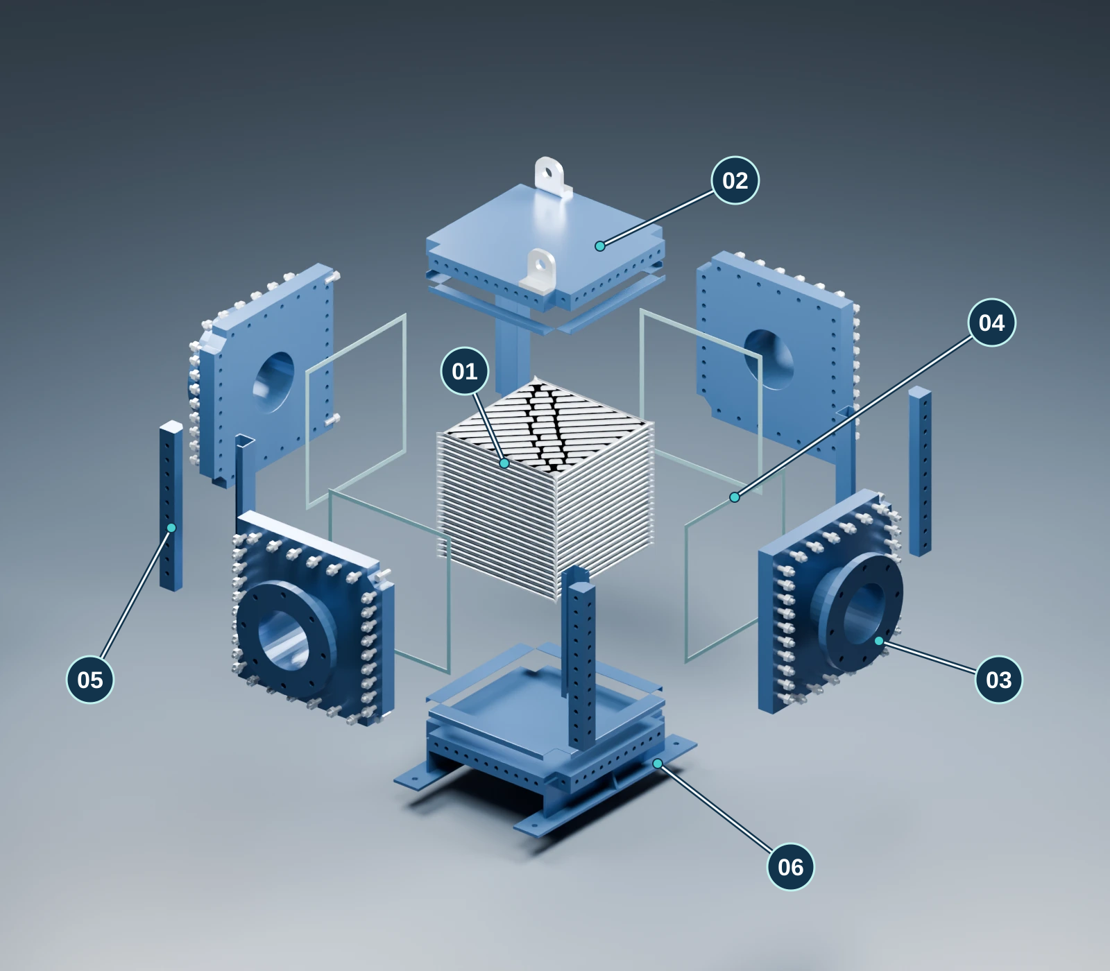
Removing the panels exposes the channel groups for inspection and cleaning. The welded plate pack remains an assembled core. Plan clearances for panel removal, tools and lifting when specifying the installation.
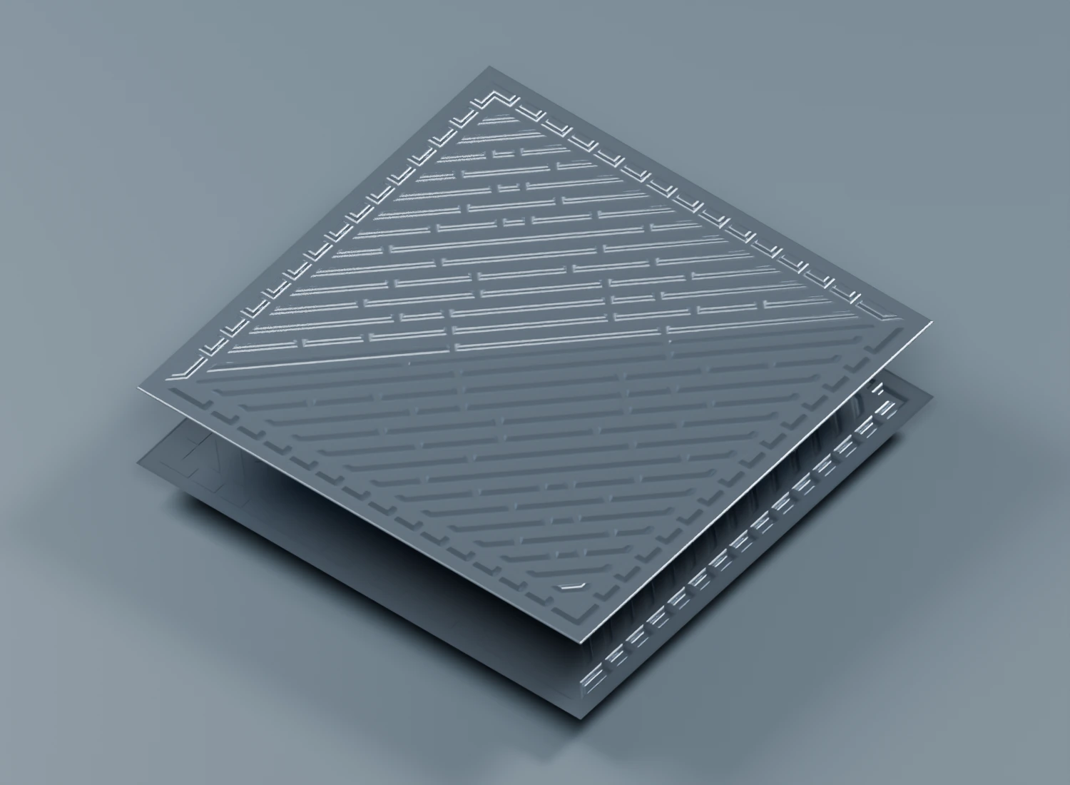
Thin corrugated metal plates form the heat transfer surface inside HEXCBLOC. Adjacent plates are arranged to create alternating channels for the two fluids.
Upward and downward embossing supports closely stacked plates and creates the flow passages. Opposing half-C edges meet at a narrow weld line around an unfilled cavity. One channel is closed along edges 1 and 3, leaving edges 2 and 4 open. The next channel closes edges 2 and 4 and leaves edges 1 and 3 open. Repeating this pattern forms two separate fluid circuits on opposite sides of each heat transfer plate.
Focused on refining, petrochemicals and chemical production — industries where hot process streams, demanding media and maintenance access shape exchanger selection.
Recover heat from hot process streams in a compact unit. Welded plate channels reduce reliance on elastomer gaskets; removable panels provide cleaning access.
Compact heat-transfer area supports capacity upgrades in crowded process units. Flow arrangement and pressure drop are selected for each liquid or vapour duty.
Consider welded channels where process temperature or chemical compatibility limits plate gaskets. Plate alloy and panel seals must match the fluid composition and concentration.
These are typical applications of welded block heat exchangers. HEXCBLOC selection requires confirmation of the fluid, plate alloy, panel seals, fouling conditions and design ratings.
Compare the model sizes, then define the plate pack and connections around your process duty.
| Model | Maximum dimensions (A × A × B), mm | Standard pressure, bar | Temperature range, °C |
|---|---|---|---|
| HEXCBLOC 15 ↗ | 280 × 280 × 540 | FV–32 | −40–300 |
| HEXCBLOC 20 ↗ | 430 × 430 × 730 | FV–32 | −40–300 |
| HEXCBLOC 30 ↗ | 500 × 500 × 1,070 | FV–32 | −40–300 |
| HEXCBLOC 40 ↗ | 600 × 600 × 1,400 | FV–32 | −40–300 |
| HEXCBLOC 50 ↗ | 840 × 840 × 2,050 | FV–32 | −40–300 |
| HEXCBLOC 75 ↗ | 1,240 × 1,240 × 3,600 | FV–32 | −40–300 |
| HEXCBLOC 120 ↗ | 2,190 × 2,190 × 3,500 | FV–32 | −40–300 |
FV = full vacuum. Dimensions are maximum envelope values A × A × B. Final dimensions, pressure and temperature ratings follow the approved project drawing and specification.
AISI 304L / 316L · Titanium · 904L · 254 SMO · Alloys selected for the medium
Graphite / PTFE, selected for operating conditions.
Start with your process data, even if you have no existing model number. The proposal defines the selected size, materials and operating envelope.
| Parameter | Your process data | Technical proposal |
|---|---|---|
| Heat load & temperatures | Required duty; inlet and outlet temperatures on both sides. | Thermal performance and selected heat transfer area. |
| Media & materials | Fluid composition, viscosity, solids and corrosion conditions. | Plate material and compatible wetted components. |
| Pressure & flow | Flow rates, operating/design pressures and allowable pressure drop. | Channel arrangement, design conditions and connection sizes. |
| Installation & documents | Space, service access, nozzle requirements and design code. | General arrangement drawing and project documentation. |
Include your requirements for datasheets, general arrangement drawings and operating documentation in your enquiry.
Yes. Share the hot- and cold-side conditions, heat load and site requirements. You can start with a process datasheet or a description of the duty; an existing equipment model is optional.
The removable panels provide access for inspection and mechanical cleaning. A suitable cleaning method and interval depend on the deposits, fluid and operating instructions. Space for maintenance should be allowed in the layout.
New equipment, more capacity or a process upgrade — start with your duty.
Replacement solutions for existing Alfa Laval Compabloc and GEA / Kelvion K°Bloc installations, subject to engineering review.
Review the welded core, plate pattern, materials, baffles and interfaces with the existing casing. Retained components require inspection.
Request replacement assessment ↗Assess a complete exchanger against the thermal duty, design conditions, nozzle arrangement, supports and available service space.
Request replacement assessment ↗Evaluate a complete-unit alternative for the existing installation. K°Bloc core interchange is not offered.
Request replacement assessment ↗Send the nameplate, datasheet, general arrangement drawing and operating conditions. Compatibility is confirmed for each project; model numbers alone do not establish a direct fit.


